Are you looking to configure a Cisco router for Internet access for the first time? Yes? Great! This post is for you then.
I am going to show you step-by-step a quick and easy way to configure a Cisco IOS router to provide Internet connectivity securely. After putting together a network design diagram, we’re going to execute the following tasks:
At the end of this post, your router should be ready to allow your users to access the Internet.
Are you ready? Let’s go.
Advertisement
Network Design Diagram
The first thing you need to do is to create a basic diagram to lay out all the IP addresses (private and public), physical interfaces (internal and external), and features you want to be turned on. Having a visual of your final network will make it easier for you to carry out the staging, testing, and implementation of your Internet router.
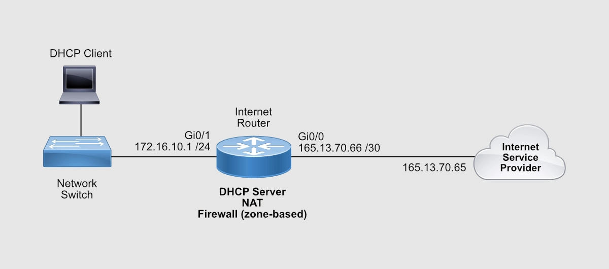
So we have the following information:
- ISP-facing interface: GigabitEthernet 0/0 (or Gi0/0)
- External/Public IP subnet: 165.13.70.64 255.255.255.252
- IP address assigned to the Internet Service Provider (ISP) end: 165.13.70.65
- IP address assigned to you (the customer): 165.13.70.66
- User-facing interface: GigabitEthernet 0/1 (or Gi0/1)
- Internal/Private IP subnet: 172.16.10.0 /24
- IP address assigned to the router: 172.16.10.1
Let’s now configure these IP addresses on the router’s interfaces.
Advertisement
Configure Router Interfaces
Your ISP should provide you with an Ethernet connection to their router. This line, however, could provide IP addresses dynamically via DHCP or statically (manually configured on the router).
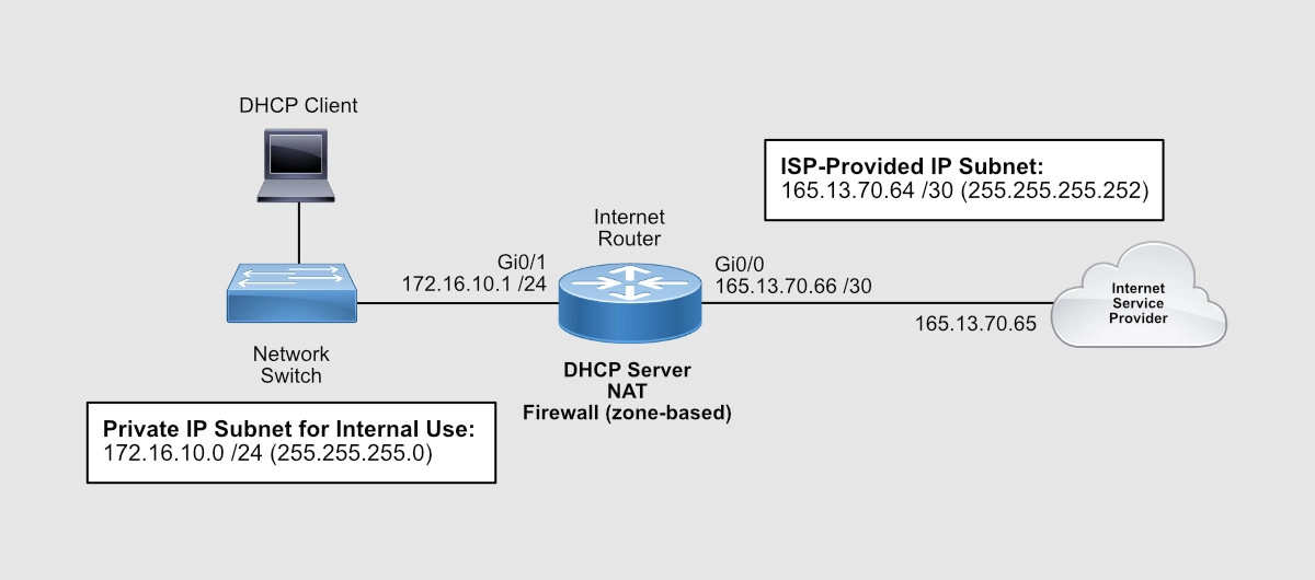
In case the ISP’s line provides IP addresses dynamically, I’m going to give you the commands to allow your router to request and receive its public IP address from the ISP. Remember, the provider’s end has to be configured to provide an IP address with the DHCP protocol, which is the protocol used to assign IP addresses.
Router#config term
Enter configuration commands, one per line.  End with CNTL/Z.
Router(config)#interface gigabitEthernet 0/0
Router(config-if)#description INTERNET LINE
Router(config-if)#ip address dhcp
Router(config-if)#no ip proxy-arp
Router(config-if)#no ip unreachables
Router(config-if)#no ip redirects
Router(config-if)#no shutdown
Router(config-if)#exit
Router(config)#
In our case, the ISP gave you the IP address you need to assign to your router’s ISP-facing interface. I like to use Gi0/0 to connect the ISP’s Ethernet line. Here are the commands to configure an IP address on your Cisco router.
Router(config)#interface gigabitEthernet 0/0
Router(config-if)#description INTERNET LINE
Router(config-if)#ip address 165.13.70.66 255.255.255.252
Router(config-if)#no ip proxy-arp
Router(config-if)#no ip redirects
Router(config-if)#no ip unreachables
Router(config-if)#no shutdown
Router(config-if)#exit
Router(config)#
Now you need to tell your router that any IP packet it doesn’t have a route for, it needs to send it to the ISP. You need to configure a default route.
Router(config)#
Router(config)#ip route 0.0.0.0 0.0.0.0 165.13.70.65
Router(config)#end
Router#
Make sure that your Interface is up.
Router#show ip interface brief
Interface                  IP-Address      OK? Method Status                Protocol
GigabitEthernet0/0         165.13.70.66    YES manual up                    up
GigabitEthernet0/1         unassigned      YES unset  administratively down down
GigabitEthernet0/2         unassigned      YES unset  administratively down down
GigabitEthernet0/3         unassigned      YES unset  administratively down down
Router#
You can test connectivity to your ISP by pinging the ISP’s end of Internet line connected to Gi0/0.
Router#ping 165.13.70.65
Type escape sequence to abort.
Sending 5, 100-byte ICMP Echos to 165.13.70.65, timeout is 2 seconds:
!!!!!
Success rate is 100 percent (5/5), round-trip min/avg/max = 23/187/293 ms
Router#
You can test Internet connectivity by pinging a public IP device on the Internet. For instance, you can ping one of Google’s DNS servers 8.8.8.8.
Router#ping 8.8.8.8
Type escape sequence to abort.
Sending 5, 100-byte ICMP Echos to 8.8.8.8, timeout is 2 seconds:
!!!!!
Success rate is 100 percent (5/5), round-trip min/avg/max = 14/38/94 ms
Router#
Let’s configure now your internal IP address on interface Gi0/1.
Router#config term
Enter configuration commands, one per line.  End with CNTL/Z.
Router(config)#interface gigabitEthernet 0/1
Router(config-if)# description INTERNAL/PRIVATE SEGMENT
Router(config-if)# ip address 172.16.10.1 255.255.255.0
Router(config-if)# no ip proxy-arp
Router(config-if)# no ip redirects
Router(config-if)# no ip unreachables
Router(config-if)# no shutdown
Router(config-if)# exit
Router(config)#
Now that your router itself has Internet connectivity, let’s configure your router to provide IP addresses to your internal devices.
Advertisement
Configure DHCP Server
A Dynamic Host Configuration Protocol (DHCP) server is a service built into your router that allows your router to distribute IP addresses of a previously configured pool of addresses.
In our example, the network’s internal subnet is 172.16.10.0 /24 and the router has been assigned the 172.16.10.1 IP address to its Gi0/1 interface. You can tell the router to start assigning IP addresses starting from 172.16.10.11 through 172.16.10.254.
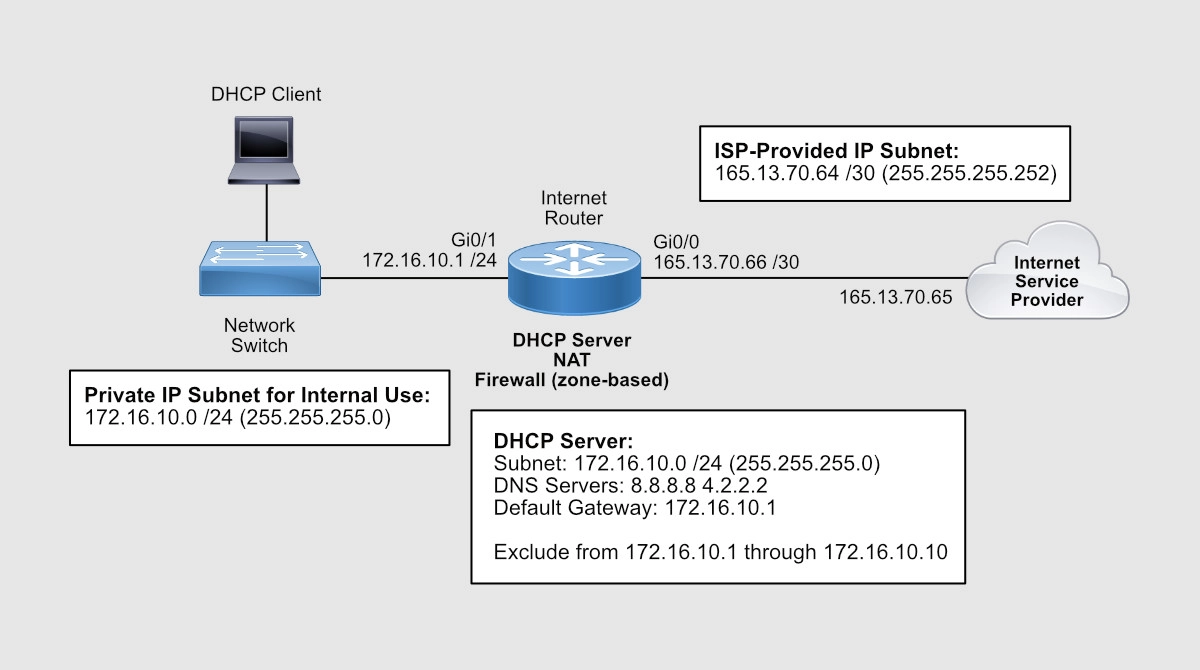
A /24 equals to 255.255.255.0. Decimal 255 is 11111111 (eight 1s) in binary. So, 255.255.255.0 equals to 11111111.11111111.11111111.0. And that is 24 bits. That’s why 255.255.255.0 is the same as a /24.
Router(config)#ip dhcp excluded-address 172.16.10.1 172.16.10.10
Router(config)#
Router(config)#ip dhcp pool INSIDE
Router(dhcp-config)# network 172.16.10.0 255.255.255.0
Router(dhcp-config)# dns-server 8.8.8.8 4.2.2.2
Router(dhcp-config)# default-router 172.16.10.1
Router(dhcp-config)#exit
Router(config)#exit
Router#
To check your DHCP Pool settings, use the show ip dhcp pool command:
Router#show ip dhcp pool

Pool INSIDE :
 Utilization mark (high/low)    : 100 / 0
 Subnet size (first/next)       : 0 / 0
 Total addresses                : 254
 Leased addresses               : 0
 Pending event                  : none
 1 subnet is currently in the pool :
 Current index        IP address range                    Leased addresses
 172.16.10.1          172.16.10.1      - 172.16.10.254     0
Router#
When a computer on the inside of the network comes up, that computer will request an IP address via a DHCP Request. When the router sees that request on its Gi0/1 interface, it’ll respond with an IP address from the pool of IPs you just configured. Since you excluded IPs from 172.16.10.1 through 172.16.10.10, the first available IP would be 172.16.10.11.
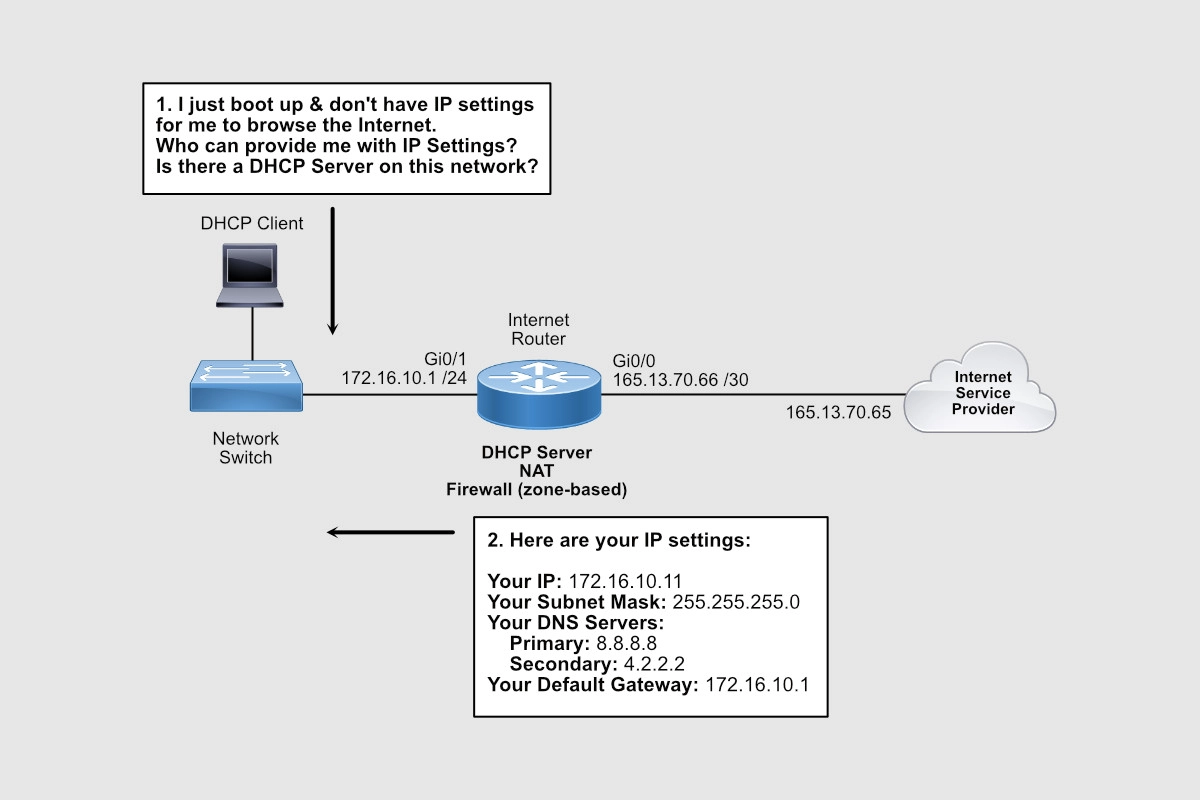
In addition to the IP address for the PC itself, the DHCP Reply message also contains the IP addresses of the DNS servers (8.8.8.8 and 4.2.2.2) and the default gateway (172.16.10.1) configured.
Notice that we’re using public DNS servers. Remember Internet communications happen in terms of IP addresses. When you type www.cisco.com on your browser, your computer sends a request to its DNS server assigned by DHCP, in our case is 8.8.8.8, and this server with an IP address related to www.cisco.com. Your browser then sends an HTTP request to that IP address to load the home page of www.cisco.com.
If 8.8.8.8 doesn’t respond, a request is sent to 4.2.2.2 as configured above.
A default gateway is used when your PC wants to talk to an IP address that belongs to anything outside its IP address group. For instance, your PC was assigned an IP address from a pool of IPs that starts with 172.16.10.1 through 172.16.10.254.
Your DHCP server, however, was also configured to exclude IPs from 172.16.10.1 through 172.16.10.10 for dynamic assigned. Nevertheless, all IPs from 172.16.10.1 through 172.16.10.254 belong to your group and therefore you can communicate with them directly. Anything outside of that group needs to be sent to the default gateway.
For that reason, when your computer needs to send a DNS request to 8.8.8.8, that request is sent to its default gateway, 172.16.10.1.
Use the show ip dhcp binding command to see what IP addresses have been assigned off the pool configured.
Router#show ip dhcp binding
Bindings from all pools not associated with VRF:
IP address          Client-ID/              Lease expiration        Type
                    Hardware address/
                    User name
172.16.10.11        0063.6973.636f.2d35.    Mar 07 2022 08:50 PM    Automatic
                    3235.342e.3030.3034.
                    2e30.3733.372d.4769.
                    302f.30
Router#
Notice that the first IP address assigned is the first IP available on the pool.
Advertisement
Configure NAT
The Internet doesn’t know how to talk to any of your PCs with an IP that starts with 172.16.10. That IP subnet is considered private, not routable on the Internet. The only public IP you have on your router is the IP address assigned to your Gi0/0 interface and that is 165.13.70.66.
Network Address Translation (NAT) is another service that can be activated on your router that allows your router to hide your private IP addresses behind your public IP. In other words, your router will convert any private IP range into a public IP or public range.
Simply put, anyone on the Internet won’t know that IP communications, such as browsing a web server, are coming from PCs with IPs within the 172.16.10.0 /24 private range. What the Internet will see is IP communications coming from 165.13.70.66 IP address. And this is thanks to NAT.
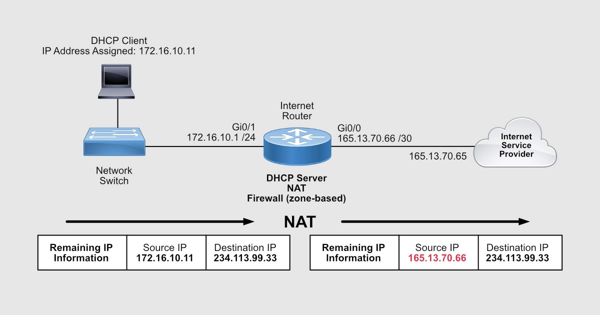
When you click on a link on a webpage, that click is a request to display the contents of the webpage the link is pointing to. That request leaves your PC as an IP packet sourced from the IP address of your PC and destined to the IP address of the web server that hosts that new webpage. Remember that the link is based on a name that is then resolved into an IP address by your DNS server.
To configure NAT on your router, enter the following commands:
Router(config)#interface gigabitEthernet 0/1
Router(config-if)#ip nat inside
Router(config-if)#exit
Router(config)#
Router(config)#interface gigabitEthernet 0/0
Router(config-if)#ip nat outside
Router(config-if)#exit
Router(config)#
Router(config)#ip access-list extended NAT-TRAFFIC
Router(config-ext-nacl)# permit ip 172.16.10.0 0.0.0.255 any
Router(config-ext-nacl)# exit
Router(config)#
Router(config)#ip nat inside source list NAT-TRAFFIC interface gigabitEthernet 0/0 overload
Router(config)#end
Router#
To look at the configuration, use the show ip nat statistics command:
Router#show ip nat statistics
Total active translations: 0 (0 static, 0 dynamic; 0 extended)
Peak translations: 1, occurred 00:03:59 ago
Outside interfaces:
  GigabitEthernet0/0
Inside interfaces:
  GigabitEthernet0/1
Hits: 200  Misses: 0
CEF Translated packets: 200, CEF Punted packets: 0
Expired translations: 1
Dynamic mappings:
-- Inside Source
[Id: 1] access-list NAT-TRAFFIC interface GigabitEthernet0/0 refcount 0

Total doors: 0
Appl doors: 0
Normal doors: 0
Queued Packets: 0
Router#
What we’re saying here is that all traffic sourced from any of the IP addresses that belong to the 172.16.10.0 /24 subnet that comes in Gi0/1, goes out Gi0/0, and is directed to ANY IP, replace that source IP of 172.16.10.X with the IP address configured on Gi0/0 interface.
So, for the Internet, traffic is coming from 165.13.70.66 and not from 172.16.10.X. In other words, 172.16.10.X is being replaced/impersonated by 165.13.70.66.
Router#show ip nat translations
Pro Inside global      Inside local       Outside local      Outside global
icmp 165.13.70.66:0    172.16.10.11:0     8.8.8.8:0          8.8.8.8:0
Router#
The Inside Local IP is the original IP. The Inside Global is the NAT IP that’s impersonating the original IP. The Outside Local and Global are the destination IPs on the Internet. In this case, a ping was executed from 172.16.10.11 to 8.8.8.8. Notice that the protocol is ICMP.
Here’s the output of web access on TCP port 80 from 172.16.10.11 to 8.8.8.8.
Router#show ip nat translations
Pro Inside global      Inside local       Outside local      Outside global
tcp 165.13.70.66:23440 172.16.10.11:23440 8.8.8.8:80         8.8.8.8:80
Router#
You should know that there are other processes, such as Port Address Translation (PAT), working at the same time to keep track of all the sources and destinations IPs and their TCP ports.
To increase security and reject unauthorized traffic coming from the Internet, you can make use of the Cisco IOS Firewall. Let’s take a look.
Advertisement
Configure Zone-Based Firewall
The IOS firewall, or Zone-Based Firewall, requires the Security License on your router, so make sure you have it.
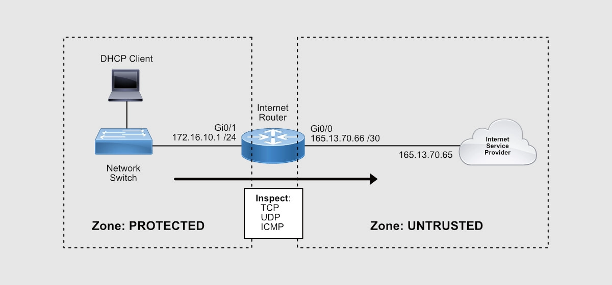
When configuring this firewall, you’re going to create two zones: the Protected Zone (internal network) and the Untrusted Zone (Internet).
This firewall will keep track of all TCP, UDP, and ICMP conversations initiated from the inside of your network that pass through the router and to the Internet. Notice that I mentioned, “initiated from the inside.”
Return traffic will then be expected by the router and allowed through towards the internal PCs that requested the traffic initially.
Any traffic initiated from the Internet will be denied!
Here’s the list of configuration commands you need to configure the Zone-Based Firewall:
Router(config)#zone security PROTECTED
Router(config-sec-zone)# description INSIDE/INTERNAL NETWORK
Router(config-sec-zone)# exit
Router(config)#
Router(config)#zone security UNTRUSTED
Router(config-sec-zone)# description INTERNET ISP
Router(config-sec-zone)# exit
Router(config)#
Router(config)#class-map type inspect match-any ALLOWED_OUTBOUND
Router(config-cmap)# match protocol tcp
Router(config-cmap)# match protocol udp
Router(config-cmap)# match protocol icmp
Router(config-cmap)# exit
Router(config)#
Router(config)#policy-map type inspect OUTBOUND
Router(config-pmap)# class type inspect ALLOWED_OUTBOUND
Router(config-pmap-c)#  inspect
Router(config-pmap-c)#  exit
Router(config-pmap)# exit
Router(config)#
Router(config)#zone-pair security PROTECTED_TO_UNTRUSTED source PROTECTED destination UNTRUSTED
Router(config-sec-zone-pair)# service-policy type inspect OUTBOUND
Router(config-sec-zone-pair)# exit
Router(config)#
Router(config)#
Router(config)#interface gigabitEthernet 0/1
Router(config-if)#zone-member security PROTECTED
Router(config-if)#exit
Router(config)#
Router(config)#interface gigabitEthernet 0/0
Router(config-if)#zone-member security UNTRUSTED
Router(config-if)#exit
Router(config)#exit
Router#
So, here are the steps:
- You create the security zones.
- You create class-maps to define what traffic you want the IOS firewall to look at – in our case TCP, UDP, and ICMP.
- You create a policy-map that will “inspect” the traffic defined by the class-map – in other words, inspect TCP, UDP, and ICMP conversations.
- You create the zone-pair where you define the direction of the traffic: where the traffic is coming from (source zone) and where it is exiting (destination zone).
- To this zone-pair, you attach the policy-map created to activate traffic inspection.
- You define what interfaces belong to the source and destination zones.
Remember that inspection enables the router to keep track of all the conversation details such as source and destination TCP and UDP ports as well as ICMP traffic.
Here’s a list of show commands for verifications:
Router#show zone security
zone self
Description: System Defined Zone

zone PROTECTED
 Description: INSIDE/INTERNAL NETWORK
 Member Interfaces:
 GigabitEthernet0/1

zone UNTRUSTED
 Description: INTERNET ISP
 Member Interfaces:
 GigabitEthernet0/0

Router#
Router#show zone-pair security
Zone-pair name PROTECTED_TO_UNTRUSTED
    Source-Zone PROTECTED  Destination-Zone UNTRUSTED
    service-policy OUTBOUND

Router#
Router#show policy-map type inspect zone-pair sessions

policy exists on zp PROTECTED_TO_UNTRUSTED
  Zone-pair: PROTECTED_TO_UNTRUSTED

  Service-policy inspect : OUTBOUND

    Class-map: ALLOWED_OUBOUND (match-any)
      Match: protocol tcp
        1 packets, 24 bytes
        30 second rate 0 bps
      Match: protocol udp
        0 packets, 0 bytes
        30 second rate 0 bps
      Match: protocol icmp
        0 packets, 0 bytes
        30 second rate 0 bps

   Inspect

    Class-map: class-default (match-any)
      Match: any
      Drop
        0 packets, 0 bytes
Router#
At this point, all your users should be able to browse the Internet. All traffic initiated from the Internet will be denied by the firewall. All traffic that comes back from the Internet as a result of requests coming from internal users will be allowed through the firewall.
Getting CCNA or CCNP Certified?

Self-paced Books. On-demand Courses. Practice Tests.
Sign up for a 10-day free trial with unlimited access!
Closing
In this post, we covered the step-by-step design and configuration of a Cisco IOS router to allow Internet access. So, at this point, your router should allow your users Internet access with the protection of Cisco’s Zone-Based Firewall.
I hope this post was informative for you.
Cheers.

Hi Alirio,
I’ve tried to test your solution on PT 8.2.
The part that i have a problem is the ISP configuration. Which PT device is used for this object ? How can i assigne my ISP address in this device ?
Can you give more explaination of this point.
Many thanks
Hi Philippe. I’m not sure I understand your question. Could you please elaborate a little bit more?
Very interesting and complete explanation how to configure cisco router as a firewall. All works fine! Thanks a lot!
I’m glad it helped. Thanks for your feedback.
great thanks for you Mr
You’re very welcome!