The purpose of this post is to give you a Nexus Virtual Port Channel (vPC) configuration example that you can use in your Cisco projects.
But first, to have a better understanding of Cisco’s Virtual Port Channel, let’s quickly go over a few concepts.
Advertisement
Nexus Virtual Port Channel Basics
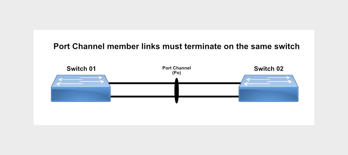
Remember that port-channel, or etherchannel, is a technology to aggregate, or bundle, multiple interfaces together into one logical interface called a port channel. Traffic is then load-balanced across each of the connections.
Port-channels provide three important benefits:
- Redundancy. If one of the member interfaces fails, traffic is redirected over the remaining links.
- Bandwidth. Increase in transmission capacity due to bundling multiple interfaces together. All interfaces are active transmission channels.
- Spanning Tree. Port-channels are seen as a single interface by Spanning-Tree protocols.
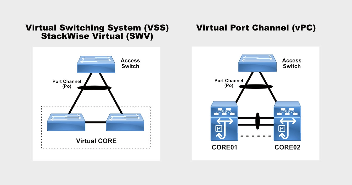
An important consideration is that all links within the port-channel must be connected to the same switch; however, Cisco’s Virtual Port-Channel, also known as Multichassis EtherChannel (MEC), is a feature on the Cisco Nexus switches that provides the ability to configure a Port-Channel across multiple switches.

Virtual Port Channel does not create a virtual switch out of two physical switches like Virtual Switching System (VSS) and StackWise Virtual (SWV) do. Virtual Port Channel bonds physical ports from two separate switches into one port channel.

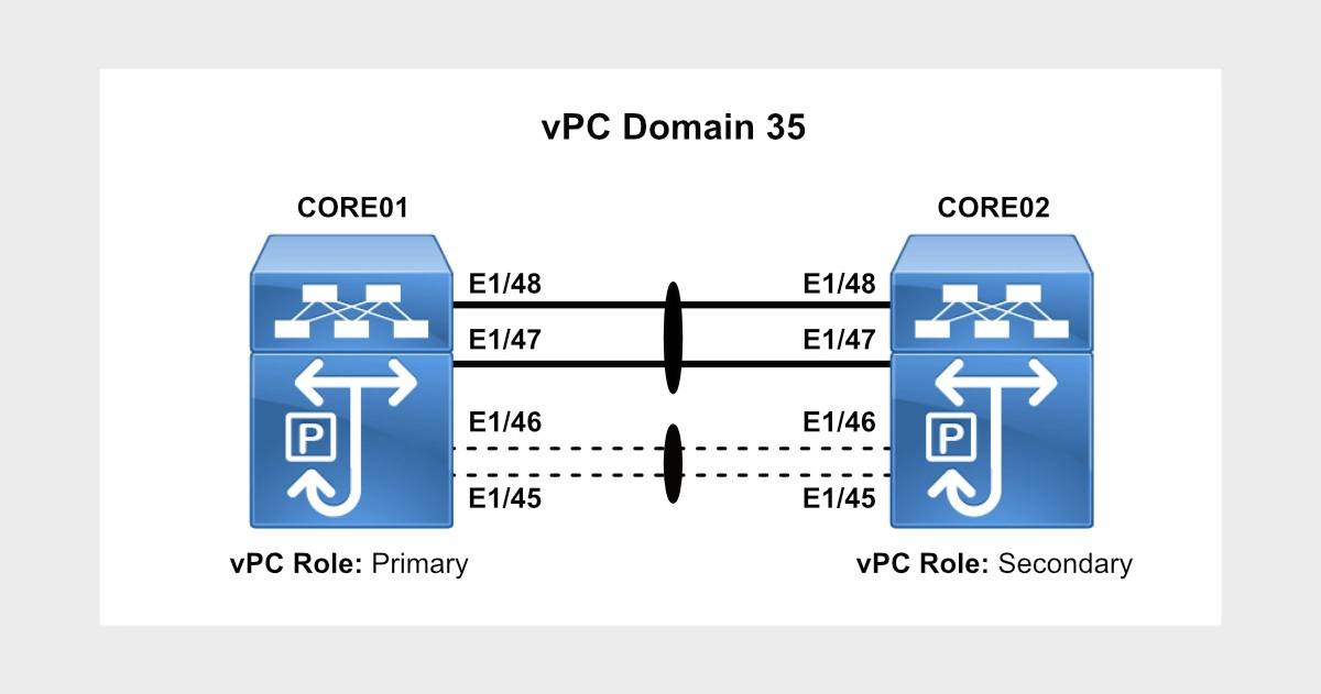
Here’s a network diagram of the vPC domain we are going to configure.

Let’s get to the vPC configuration of a pair of Nexus switches.
Advertisement
Nexus Virtual Port Channel (vPC) Configuration Example on Primary Switch
Nexus vPC configuration example on CORE01.
switch# config term
Enter configuration commands, one per line. End with CNTL/Z.
switch(config)#
switch(config)# hostname CORE01
CORE01(config)# feature vpc
CORE01(config)# feature lacp
CORE01(config)#
CORE01(config)# vrf context VPC_KEEPALIVE
CORE01(config-vrf)#  exit
CORE01(config)# interface port-channel45
CORE01(config-if)#   no switchport
CORE01(config-if)#   description vPC PEER KEEPALIVE
CORE01(config-if)#   vrf member VPC_KEEPALIVE
Warning: Deleted all L3 config on interface port-channel45
CORE01(config-if)#   ip address 1.1.1.1/30
CORE01(config-if)#   exit
CORE01(config)#
CORE01(config)# interface Ethernet1/45-46
CORE01(config-if-range)#   no switchport
CORE01(config-if-range)#   description Po45 vPC KEEPALIVE MEMBER
CORE01(config-if-range)#   channel-group 45 mode active
CORE01(config-if-range)#   no shutdown
CORE01(config-if-range)#   exit
CORE01(config)#
CORE01(config)# vpc domain 35
CORE01(config-vpc-domain)#   peer-switch
CORE01(config-vpc-domain)#   role priority 5
Note:
 Change will take effect after user has:
   1. Triggered "vpc role preempt" (non-disruptive - no traffic loss on STP root switch)
OR 2. Re-initd the vPC peer-link (disruptive)
Warning:
 !!:: vPCs will be flapped on current primary vPC switch while attempting option 2 ::!!
CORE01(config-vpc-domain)#   system-priority 20000
CORE01(config-vpc-domain)#   peer-keepalive destination 1.1.1.2 source 1.1.1.1 vrf VPC_KEEPALIVE
CORE01(config-vpc-domain)#   peer-gateway
CORE01(config-vpc-domain)#   layer3 peer-router
CORE01(config-vpc-domain)#   ip arp synchronize
CORE01(config-vpc-domain)#   auto-recovery
Warning:
 Enables restoring of vPCs in a peer-detached state after reload, will wait for 240 seconds to determine if peer is un-reachable
2002 Aug  4 12:30:27 CORE01 %$ VDC-1 %$ %STP-2-VPC_PEERSWITCH_CONFIG_ENABLED: vPC peer-switch configuration is enabled. Please make sure to configure spanning tree "bridge" priority as per recommended guidelines to make vPC peer-switch operational.
CORE01(config-vpc-domain)#   exit
CORE01(config)#
CORE01(config)# vlan 999
CORE01(config-vlan)# name NATIVE
CORE01(config-vlan)# exit
CORE01(config)#
CORE01(config)# interface port-channel47
CORE01(config-if)#   description vPC PEERLINK
CORE01(config-if)#   switchport
CORE01(config-if)#   switchport mode trunk
CORE01(config-if)#   switchport trunk native vlan 999
CORE01(config-if)#   spanning-tree port type network
CORE01(config-if)#   vpc peer-link
Please note that spanning tree port type is changed to "network" port type on vPC peer-link.
This will enable spanning tree Bridge Assurance on vPC peer-link provided the STP Bridge Assurance
(which is enabled by default) is not disabled.
CORE01(config-if)#   exit
CORE01(config)#
CORE01(config)# interface e1/47-48
CORE01(config-if-range)#   description Po47 vPC PEERLINK MEMBER
CORE01(config-if-range)#   switchport
CORE01(config-if-range)#   switchport mode trunk
CORE01(config-if-range)#   switchport trunk native vlan 999
CORE01(config-if-range)#   spanning-tree port type network
CORE01(config-if-range)#   channel-group 47 mode active
CORE01(config-if-range)#   no shutdown
CORE01(config-if-range)#   exit
CORE01(config)# end
CORE01#
Let’s take a look at the config on vPC Secondary Peer (CORE02).
Advertisement
Nexus Virtual Port Channel (vPC) Configuration Example on Secondary Switch
Nexus vPC configuration on CORE02.
switch(config)#
switch(config)# hostname CORE02
CORE02(config)#
CORE02(config)# feature vpc
CORE02(config)# feature lacp
CORE02(config)#
CORE02(config)# vrf context VPC_KEEPALIVE
CORE02(config-vrf)#  exit
CORE02(config)#
CORE02(config)# interface port-channel45
CORE02(config-if)#   no switchport
CORE02(config-if)#   description vPC PEER KEEPALIVE
CORE02(config-if)#   vrf member VPC_KEEPALIVE
Warning: Deleted all L3 config on interface port-channel45
CORE02(config-if)#   ip address 1.1.1.2/30
CORE02(config-if)#   exit
CORE02(config)#
CORE02(config)# interface Ethernet1/45-46
CORE02(config-if-range)#   no switchport
CORE02(config-if-range)#   description Po45 vPC KEEPALIVE MEMBER
CORE02(config-if-range)#   channel-group 45 mode active
CORE02(config-if-range)#   no shutdown
CORE02(config-if-range)#   exit
CORE02(config)#
CORE02(config)# vpc domain 35
CORE02(config-vpc-domain)#   peer-switch
CORE02(config-vpc-domain)#   role priority 10
Note:
 Change will take effect after user has:
   1. Triggered "vpc role preempt" (non-disruptive - no traffic loss on STP root switch)
OR 2. Re-initd the vPC peer-link (disruptive)
Warning:
 !!:: vPCs will be flapped on current primary vPC switch while attempting option 2 ::!!
CORE02(config-vpc-domain)#   system-priority 20000
CORE02(config-vpc-domain)#   peer-keepalive destination 1.1.1.1 source 1.1.1.2 vrf VPC_KEEPALIVE
CORE02(config-vpc-domain)#   peer-gateway
CORE02(config-vpc-domain)#   layer3 peer-router
CORE02(config-vpc-domain)#   ip arp synchronize
CORE02(config-vpc-domain)#   auto-recovery
Warning:
 Enables restoring of vPCs in a peer-detached state after reload, will wait for 240 seconds to determine if peer is un-reachable
2002 Aug  4 13:54:07 CORE02 %$ VDC-1 %$ %STP-2-VPC_PEERSWITCH_CONFIG_ENABLED: vPC peer-switch configuration is enabled. Please make sure to configure spanning tree "bridge" priority as per recommended guidelines to make vPC peer-switch operational.
CORE02(config-vpc-domain)#   exit
CORE02(config)#
CORE01(config)# vlan 999
CORE01(config-vlan)# name NATIVE
CORE01(config-vlan)# exit
CORE02(config)# interface port-channel47
CORE02(config-if)#   description vPC PEERLINK
CORE02(config-if)#   switchport
CORE02(config-if)#   switchport mode trunk
CORE02(config-if)#   switchport trunk native vlan 999
CORE02(config-if)#   spanning-tree port type network
CORE02(config-if)#   vpc peer-link
Please note that spanning tree port type is changed to "network" port type on vPC peer-link.
This will enable spanning tree Bridge Assurance on vPC peer-link provided the STP Bridge Assurance
(which is enabled by default) is not disabled.
CORE02(config-if)#   exit
CORE02(config)#
CORE02(config)# interface e1/47-48
CORE02(config-if-range)#   description Po47 vPC PEERLINK MEMBER
CORE02(config-if-range)#   switchport
CORE02(config-if-range)#   switchport mode trunk
CORE02(config-if-range)#   switchport trunk native vlan 999
CORE02(config-if-range)#   spanning-tree port type network
CORE02(config-if-range)#   channel-group 47 mode active
CORE02(config-if-range)#   no shutdown
CORE02(config-if-range)#   exit
CORE02(config)#
CORE02(config)# exit
CORE02#
Let’s now run some vPC verification commands on both vPC Peers.
Advertisement
Nexus Virtual Port Channel (vPC) Verification on Primary Switch
Let’s take a look at some vPC verification commands on the Primary Nexus switch (CORE01).
CORE01#
CORE01# show vpc
Legend:
                (*) - local vPC is down, forwarding via vPC peer-link

vPC domain id                     : 35
Peer status                       : peer adjacency formed ok
vPC keep-alive status             : peer is alive
Configuration consistency status  : success
Per-vlan consistency status       : success
Type-2 consistency status         : success
vPC role                          : primary
Number of vPCs configured         : 0
Peer Gateway                      : Enabled
Dual-active excluded VLANs        : -
Graceful Consistency Check        : Enabled
Auto-recovery status              : Enabled, timer is off.(timeout = 240s)
Delay-restore status              : Timer is off.(timeout = 30s)
Delay-restore SVI status          : Timer is off.(timeout = 10s)
Operational Layer3 Peer-router    : Enabled

vPC Peer-link status
---------------------------------------------------------------------
id    Port   Status Active vlans
--    ----   ------ -------------------------------------------------
1     Po47   up     1,999

CORE01#
CORE01# show vpc peer-keepalive

vPC keep-alive status             : peer is alive
--Peer is alive for             : (324173) seconds, (632) msec
--Send status                   : Success
--Last send at                  : 2002.08.09 08:04:35 607 ms
--Sent on interface             : Po45
--Receive status                : Success
--Last receive at               : 2002.08.09 08:04:35 608 ms
--Received on interface         : Po45
--Last update from peer         : (0) seconds, (636) msec

vPC Keep-alive parameters
--Destination                   : 1.1.1.2
--Keepalive interval            : 1000 msec
--Keepalive timeout             : 5 seconds
--Keepalive hold timeout        : 3 seconds
--Keepalive vrf                 : VPC_KEEPALIVE
--Keepalive udp port            : 3200
--Keepalive tos                 : 192
CORE01#
CORE01#
CORE01# show vpc role

vPC Role status
----------------------------------------------------
vPC role                        : primary
Dual Active Detection Status    : 0
vPC system-mac                  : 00:23:04:ee:be:23
vPC system-priority             : 20000
vPC local system-mac            : f8:6b:d9:b8:3f:bc
vPC local role-priority         : 5
vPC local config role-priority  : 5
vPC peer system-mac             : f8:6b:d9:b8:4f:c1
vPC peer role-priority          : 10
vPC peer config role-priority   : 10
CORE01#
Advertisement
Nexus Virtual Port Channel (vPC) Verification on Secondary Switch
And now, let’s look at the same vPC verification commands on the Secondary Nexus switch (CORE02).
CORE02# show vpc
Legend:
                (*) - local vPC is down, forwarding via vPC peer-link

vPC domain id                     : 35
Peer status                       : peer adjacency formed ok
vPC keep-alive status             : peer is alive
Configuration consistency status  : success
Per-vlan consistency status       : success
Type-2 consistency status         : success
vPC role                          : secondary
Number of vPCs configured         : 0
Peer Gateway                      : Enabled
Dual-active excluded VLANs        : -
Graceful Consistency Check        : Enabled
Auto-recovery status              : Enabled, timer is off.(timeout = 240s)
Delay-restore status              : Timer is off.(timeout = 30s)
Delay-restore SVI status          : Timer is off.(timeout = 10s)
Operational Layer3 Peer-router    : Enabled

vPC Peer-link status
---------------------------------------------------------------------
id    Port   Status Active vlans
--    ----   ------ -------------------------------------------------
1     Po47   up     1,999

CORE02#
CORE02# show vpc peer-keepalive

vPC keep-alive status             : peer is alive
--Peer is alive for             : (324233) seconds, (320) msec
--Send status                   : Success
--Last send at                  : 2002.08.09 09:21:01 443 ms
--Sent on interface             : Po45
--Receive status                : Success
--Last receive at               : 2002.08.09 09:21:01 444 ms
--Received on interface         : Po45
--Last update from peer         : (0) seconds, (96) msec

vPC Keep-alive parameters
--Destination                   : 1.1.1.1
--Keepalive interval            : 1000 msec
--Keepalive timeout             : 5 seconds
--Keepalive hold timeout        : 3 seconds
--Keepalive vrf                 : VPC_KEEPALIVE
--Keepalive udp port            : 3200
--Keepalive tos                 : 192
CORE02#
CORE02#
CORE02# show vpc role

vPC Role status
----------------------------------------------------
vPC role                        : secondary
Dual Active Detection Status    : 0
vPC system-mac                  : 00:23:04:ee:be:23
vPC system-priority             : 20000
vPC local system-mac            : f8:6b:d9:b8:4f:c1
vPC local role-priority         : 10
vPC local config role-priority  : 10
vPC peer system-mac             : f8:6b:d9:b8:3f:bc
vPC peer role-priority          : 5
vPC peer config role-priority   : 5
CORE02#
Advertisement
Nexus Virtual Port Channel (vPC) Feature Enhancements
Let’s quickly understand better what some of the commands under the vPC domain process mean:
- Peer-switch. The vPC peer-switch command causes both vPC peer switches to have the same Bridge ID, so from the perspective of Spanning Tree, both peer switches appear as if they were one. Spanning Tree settings must be identical on both vPC peer switches.
- Role priority. The lower role priority becomes the primary vPC peer.
- System priority. With LACP, we can have up to 16 Ethernet ports of the same type. Up to eight ports can be active, and up to eight ports can be in standby mode. When there are more than eight ports in an LACP channel-group, the switch on the controlling end of the link uses port priorities to determine which ports are bundled into the channel and which ports are put in hot-standby mode. By lowering the system priority, we guarantee that our peer partner (i.e. access switch or other vPC pair) would not be able to take any decision in terms of the aggregation capabilities/advertisement.
- Peer-gateway. The vPC peer-gateway command allows both switches to use the same MAC address for ARP replies to avoid sending traffic across the vPC Peer Link. In other words, if an access switch needs to send traffic to the vPC core to, let’s say, VLAN 20’s SVI, if traffic in one instance is sent over link 1 to Core 1, Core 1 can receive and process the traffic. If in another instance, the same access switch needs to send traffic to VLAN 20’s SVI but this time it sends that traffic over link 2 to Core 2, Core 2 still can process that traffic instead of sending it over to Core 1 across the peer link.
- Layer3 peer-router. The layer3 peer-router command enables routing adjacencies of devices other than the Nexus switches across the vPC Peer Link. For instance, if a router is connected to one of the switches, its routing adjacency traffic needs to pass through one switch to get to the second. This used to be an unsupported configuration, but the layer3 peer-router command makes it possible.
- IP arp synchronize. When the vPC peer-link fails and then recovers, the vPC ARP Synchronize feature performs an ARP bulk synchronization over the peer link from the vPC primary peer switch to vPC secondary peer device thus improving convergence time.
- Auto-recovery. This feature enhancement assists to provide a backup mechanism in case of a vPC peer-link failure followed by a vPC primary peer device failure.
Spanning Tree values must match between the two switches. Before enabling the vPC Peer Switch enhancement, Spanning Tree priority configuration for all vPC VLANs must be modified so that it is identical between both vPC peers.
Advertisement
Nexus Virtual Port Channel (vPC) vs. Traditional Port Channel Configuration
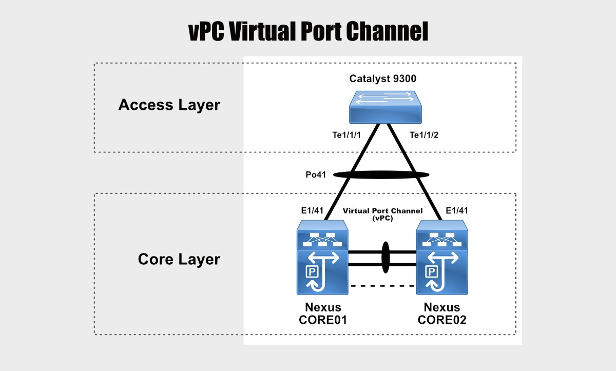
At this point, you can configure a port channel on an external switch and link it up to the two Nexus switches on ports configured as Virtual Port Channels.

I happen to have this configuration already pre-configured on a pair of Nexus switches and a Catalyst 9300 switch.
Here’s the vPC port channel configuration and verification on both Nexus switches.
CORE01# show running-config interface port-channel 41

!Command: show running-config interface port-channel41
!No configuration change since last restart
!Time: Fri Aug  9 14:58:39 2002

version 9.3(8) Bios:version 5.4.1

interface port-channel41
  description Cat9300-SW01 DMZ
  switchport mode trunk
  switchport trunk native vlan 999
  vpc 41

CORE01#
CORE01# show running-config interface ethernet 1/41

!Command: show running-config interface Ethernet1/41
!No configuration change since last restart
!Time: Fri Aug  9 14:59:25 2002

version 9.3(8) Bios:version 5.4.1

interface Ethernet1/41
  description Po41 Cat9300-SW01 DMZ T1/1/1
  switchport mode trunk
  switchport trunk native vlan 999
  channel-group 41 mode active

CORE01#
CORE01# show port-channel summary interface port-channel 41
Flags:  D - Down        P - Up in port-channel (members)
        I - Individual  H - Hot-standby (LACP only)
        s - Suspended   r - Module-removed
        b - BFD Session Wait
        S - Switched    R - Routed
        U - Up (port-channel)
        p - Up in delay-lacp mode (member)
        M - Not in use. Min-links not met
--------------------------------------------------------------------------------
Group Port-       Type     Protocol  Member Ports
      Channel
--------------------------------------------------------------------------------
41    Po41(SU)    Eth      LACP      Eth1/41(P)
CORE01#
CORE02# show running-config interface port-channel 41

!Command: show running-config interface port-channel41
!No configuration change since last restart
!Time: Fri Aug  9 16:15:32 2002

version 9.3(8) Bios:version 5.4.1

interface port-channel41
  description Cat9300-SW01 DMZ
  switchport mode trunk
  switchport trunk native vlan 999
  vpc 41

CORE02#
CORE02# show running-config interface ethernet 1/41

!Command: show running-config interface Ethernet1/41
!No configuration change since last restart
!Time: Fri Aug  9 16:15:46 2002

version 9.3(8) Bios:version 5.4.1

interface Ethernet1/41
  description Po41 Cat9300-SW01 DMZ T1/1/2
  switchport mode trunk
  switchport trunk native vlan 999
  channel-group 41 mode active

CORE02#
CORE02# show port-channel summary interface port-channel 41
Flags:  D - Down        P - Up in port-channel (members)
        I - Individual  H - Hot-standby (LACP only)
        s - Suspended   r - Module-removed
        b - BFD Session Wait
        S - Switched    R - Routed
        U - Up (port-channel)
        p - Up in delay-lacp mode (member)
        M - Not in use. Min-links not met
--------------------------------------------------------------------------------
Group Port-       Type     Protocol  Member Ports
      Channel
--------------------------------------------------------------------------------
41    Po41(SU)    Eth      LACP      Eth1/41(P)
CORE02#
And here’s the port channel configuration on the Catalyst 9300 switch.
IOS-Cat9300#show running-config interface port-channel 41
Building configuration...

Current configuration : 136 bytes
!
interface Port-channel41
 description NEXUS DMZ
 switchport trunk native vlan 999
 switchport mode trunk
 switchport nonegotiate
end

IOS-Cat9300#
IOS-Cat9300#show running-config interface tenGigabitEthernet 1/1/1
Building configuration...

Current configuration : 189 bytes
!
interface TenGigabitEthernet1/1/1
 description Po41 NEXUS DMZ-01 E1/41
 switchport trunk native vlan 999
 switchport mode trunk
 switchport nonegotiate
 channel-group 41 mode active
end

IOS-Cat9300#show running-config interface tenGigabitEthernet 1/1/2
Building configuration...

Current configuration : 189 bytes
!
interface TenGigabitEthernet1/1/2
 description Po41 NEXUS DMZ-02 E1/41
 switchport trunk native vlan 999
 switchport mode trunk
 switchport nonegotiate
 channel-group 41 mode active
end

IOS-Cat9300#
IOS-Cat9300#show etherchannel summary
Flags:  D - down        P - bundled in port-channel
        I - stand-alone s - suspended
        H - Hot-standby (LACP only)
        R - Layer3      S - Layer2
        U - in use      f - failed to allocate aggregator

        M - not in use, minimum links not met
        u - unsuitable for bundling
        w - waiting to be aggregated
        d - default port

        A - formed by Auto LAG


Number of channel-groups in use: 1
Number of aggregators:           1

Group  Port-channel  Protocol    Ports
------+-------------+-----------+-----------------------------------------------
41     Po41(SU)        LACP        Te1/1/1(P)      Te1/1/2(P)

IOS-Cat9300#
Getting CCNA or CCNP Certified?

Self-paced Books. On-demand Courses. Practice Tests.
Sign up for a 10-day free trial with unlimited access!
Closing
In this post, we covered some basic concepts on port channels and the advantage of Nexus Virtual Port Channels, or vPCs. We also built a vPC Domain on a pair of Cisco Nexus switches and ran verification commands. And lastly, we built a traditional port channel on an IOS-based switch like the Catalyst 9300 and linked it up to a vPC on the Nexus pair.
I hope this post was informative. Please, let me know of any questions or comments below.
Cheers.
